


Tel: +86-131-8042-1118
E-mail:
E-mail:
26 Huanghai Road, Leting Economic Development Zone, Hebei Province, China


Views: 0 Author: Site Editor Publish Time: 2026-08-01 Origin: Site


Commercial construction and industrial maintenance face increasing margin pressure every quarter. Traditional access methods often create severe labor bottlenecks on site, slowing down subsequent trades and extending project timelines. Project managers must navigate the tension between the high initial capital expenditure of modular scaffolding and the hidden, compounding costs of labor-intensive alternatives like tube-and-clamp setups. When you rely on older methods, you pay for the extra hours your crew spends measuring, leveling, and tightening individual fittings. This guide serves as an evidence-based framework for evaluating whether a system scaffold aligns with specific project geometries, load requirements, and long-term procurement strategies. We will break down the structural mechanics, compare field performance against legacy systems, and outline the exact site conditions that justify the transition to modular access equipment.
Labor vs. Material Economics: System scaffolds require higher upfront investment but drastically reduce erection and dismantling (E&D) labor hours compared to traditional methods.
Structural Standardization: The transition to node-based modular systems (specifically the Ringlock Scaffolding System) offers superior load-bearing predictability and geometric adaptability.
Compliance and Safety: Pre-engineered connections eliminate the variability of manual clamp tightening, standardizing safety and simplifying compliance inspections.
Procurement Reality: Mixing components from different manufacturers introduces significant liability and structural risks; vendor lock-in is a critical evaluation factor.
Modern access solutions require a fundamental shift from loose tubes and fittings to prefabricated, standardized components. A modular framework relies on engineered node points rather than friction-based clamps. This node-point connection methodology allows for multi-directional bracing without specialized tools. Workers connect horizontal and diagonal members to vertical posts at fixed intervals. This approach guarantees structural geometry and eliminates the guesswork associated with manual layout.
When crews build with loose tubes, they must constantly check plumb and level. The modular approach builds these checks directly into the components. The fixed intervals on the vertical posts force the structure into a square, plumb alignment as long as the base is properly leveled. This inherent geometric stability reduces the reliance on highly experienced scaffold builders for basic structural integrity, allowing newer crew members to assemble bays rapidly under supervision.
Vertical standards act as the primary load-bearing uprights. They feature fixed connection points, typically rosettes or cups, welded at regular intervals (usually every 500mm). The Ringlock Ledger functions as the horizontal runner. It dictates the bay length and provides essential structural rigidity to the entire framework. Diagonal braces connect across bays to prevent sway and handle lateral loads.
Base jacks provide leveling on uneven ground, while standardized decking planks lock securely into the ledgers to create safe working platforms. To understand the assembly, consider the following component breakdown:
Base Collars: Sit over the base jacks to provide the initial node point for the bottom ledgers.
Standards: The vertical tubes that transfer the load to the ground.
Ledgers: Horizontal tubes that form the guardrails and support the decks.
Diagonal Braces: Tubes with pivoting wedge heads that provide lateral stability.
Steel Planks: Perforated, non-slip decks that hook directly over the ledgers.
Toe Boards: Prevent tools and materials from falling off the working platform.
Erection speed heavily favors modular designs. Node-locking mechanisms require only a hammer blow to secure, whereas tube and clamp systems demand manual wrench tightening for every single fitting. This difference translates to massive labor hour reductions on large-scale industrial sites. Tube and clamp offers infinite micro-adjustments for highly irregular spaces. Conversely, modular systems rely on fixed node increments. This requires more precise initial planning but yields faster execution.
Consider a standard 10-meter run of scaffolding. A tube and clamp crew must measure the distance for every ledger, attach right-angle couplers, tighten the nuts, check the level, and then repeat the process. A modular crew simply drops the ledgers into the rosettes and hammers the wedges home. The time savings compound exponentially as the structure grows taller and more complex.
Frame scaffolding is ideal for flat, linear facades and low-rise masonry work. It struggles with complex industrial geometries like cylinders, boilers, or structural overhangs. Modular systems navigate these obstacles effortlessly due to their multi-directional nodes. Furthermore, modular systems support significantly higher load capacities. They can reach greater heights safely because the node connections distribute forces more efficiently through the vertical standards.
Here is a direct comparison of the two methods:
Feature | Frame Scaffolding | Modular System |
|---|---|---|
Geometry | Strictly linear, flat facades | Multi-directional, complex shapes |
Load Capacity | Light to medium duty | Heavy duty, industrial loads |
Height Limits | Generally restricted without heavy engineering | Capable of extreme heights with proper ties |
Component Weight | Heavy, bulky frames | Individual, manageable tubes |
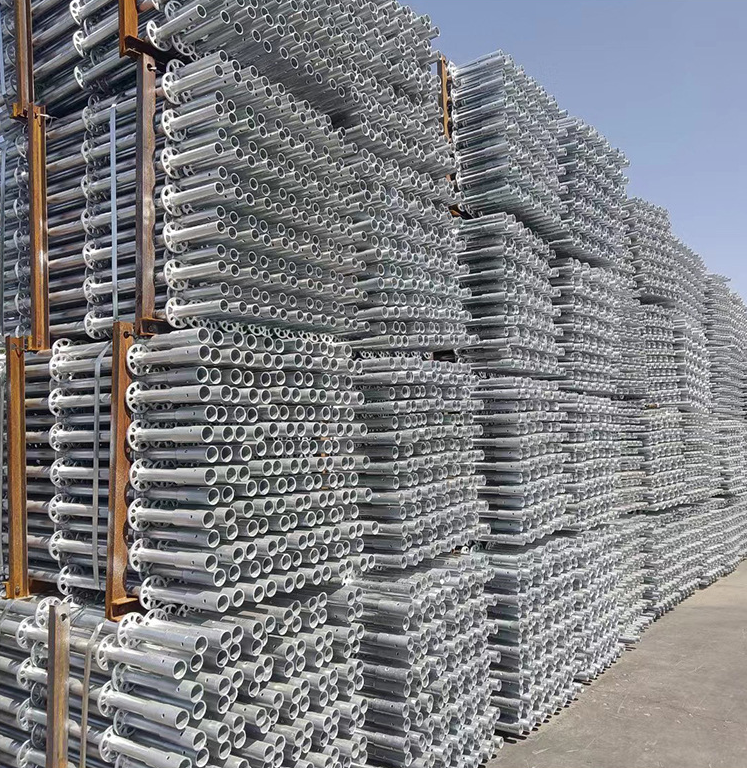
The Ringlock Scaffolding System centers on the engineered 8-hole rosette. This central node allows up to eight connections in a single plane. Four small holes accommodate right-angle ledgers, while four larger holes permit complex-angle bracing. The wedge-lock mechanism secures the joint. A captive wedge on the end of a ledger or brace slides into the rosette. A worker hammers the wedge firmly into place. This action creates a rigid, moment-resisting joint that prevents structural deflection.
The genius of the rosette lies in its simplicity and strength. When the wedge is driven home, it pulls the ledger head tight against the vertical standard. This metal-on-metal contact transfers loads directly through the standard rather than relying solely on the shear strength of the wedge. This design minimizes sway and provides a remarkably stiff working platform, even at significant heights.
Manufacturers utilize high-tensile steel to construct these components. This material choice maximizes the strength-to-weight ratio, allowing for easier manual handling without sacrificing capacity. The rosette design distributes dead and live loads evenly across the vertical standard. Engineers classify these setups into light, medium, and heavy-duty load classes based on component dimensions and bay sizes. Proper configuration ensures the structure safely supports heavy masonry materials, industrial equipment, and multiple personnel simultaneously.
Light Duty: 25 pounds per square foot (psf). Used for inspection, painting, and light maintenance.
Medium Duty: 50 psf. Used for bricklaying, plastering, and general construction.
Heavy Duty: 75 psf. Used for stone masonry, heavy material storage, and industrial pipefitting.
Complex geometries demand adaptable access solutions. Refineries, offshore rigs, shipyards, and intricate architectural facades represent ideal use cases. The geometric rigidity of these frameworks outperforms alternatives when navigating dense pipework or curved surfaces. Technological integration further enhances deployment. Teams use 3D Building Information Modeling (BIM) to model complex structures digitally before physical assembly. Unconventional applications also benefit from this adaptability. Teams deploy these frameworks for temporary environmental containment structures, suspended offshore platforms, cleanrooms, and large-scale event staging.
In a refinery setting, pipes and vessels rarely follow straight lines. A modular setup allows crews to build around these obstacles by varying bay sizes and utilizing the angled holes on the rosettes. This flexibility prevents the need for dangerous cantilevered platforms or unsupported spans. The ability to integrate with BIM software means engineers can clash-detect the scaffold design against the permanent structure, ensuring a perfect fit before the first truck arrives on site.
Calculating return on investment requires analyzing local labor rates against equipment costs. High labor costs justify the premium price of modular components. The threshold occurs when the erection speed offsets the initial capital outlay. Project managers must evaluate the total labor hours saved during both assembly and dismantling phases. Faster turnaround times also reduce overall project duration, generating indirect savings through earlier facility commissioning or reduced downtime during industrial turnarounds.
If your local labor rates are high, the speed of modular assembly will quickly pay for the equipment. Conversely, in regions with very low labor costs, the upfront investment in modular gear might take longer to recoup. You must track your E&D hours meticulously to understand your true costs. A reduction of just 20% in erection time can swing a project from a loss to a profit.
Wedge-lock and cup-lock mechanisms translate directly into measurable labor hour reductions. Crews assemble and dismantle bays rapidly without measuring or leveling every individual tube. Standardized component lengths streamline staging and material handling. Logistics teams can palletize and transport identical ledgers and standards efficiently. This standardization reduces crane lifts and minimizes material bottlenecks at the workface.
Dismantling is often where the greatest time savings occur. With tube and clamp, rusted threads and damaged nuts can slow the teardown process to a crawl. With a wedge-lock design, a single hammer strike releases the connection, allowing crews to strip the structure rapidly. This speed is critical during plant shutdowns where every hour of downtime costs the facility money.
Modular components maintain a predictable logistical footprint. They stack neatly in racks, optimizing yard space and transport capacity. However, inventory management presents challenges. Inventory shrinkage remains a reality on large sites. Replacing proprietary ledgers and captive wedges requires sourcing from the original manufacturer. Accurate tracking systems are essential to prevent component loss and maintain fleet integrity.
To manage inventory effectively, consider these practices:
Use dedicated steel pallets for specific component lengths.
Implement barcode or RFID tracking for high-value items.
Conduct weekly yard audits to identify missing gear early.
Establish clear laydown areas on site to prevent components from being buried in the mud.
Pre-engineered connections drastically reduce human error during assembly. Fixed nodes eliminate the risk of loose friction clamps slipping under load. Structured, on-site safety training programs minimize operational risks and standardize safe operating procedures. Specialized training ensures crews erect modular systems to strict OSHA and HSE standards. Management must never assume that modular designs are foolproof; rigorous training remains mandatory for safe deployment.
A common mistake is assuming that because the system is modular, anyone can build it. While the connections are simpler, the structural principles remain the same. Crews must understand how to properly install ties to the building, how to brace the structure against wind loads, and how to inspect the components for damage. A damaged rosette or a bent ledger compromises the entire bay.
Hot-dipped galvanized components offer superior durability compared to painted frames or raw steel tubes. The galvanization process protects the steel from internal and external corrosion. Materials must withstand extreme environmental degradation. UV radiation exposure damages safety netting and identification tags, while marine and corrosive industrial atmospheres attack the steel itself. Asset lifespans in harsh environments dictate depreciation schedules. High-quality galvanized fleets often remain in service for decades, justifying the initial investment.
When evaluating the lifecycle, look at the maintenance requirements. Painted frames require constant touch-ups to prevent rust. Galvanized modular gear requires minimal maintenance beyond basic cleaning and inspection. Over a ten-year period, the maintenance savings alone can offset the higher initial purchase price.
Committing to a specific proprietary system involves significant trade-offs. Mixing brands is generally prohibited. Buyers must evaluate supply chain availability and local rental yard inventory before committing. A robust regional supply chain ensures access to additional components during peak project demands. Generic alternatives exist, but they may lack the stringent quality control and engineering support provided by established tier-one manufacturers.
Before purchasing a fleet, survey the rental yards in your operating radius. If you buy a system that no one else in your area uses, you will be stranded when you need extra gear for a large job. Choose a system with a deep local rental pool to ensure you can scale up and down as project demands dictate.
Mixing components from different manufacturers introduces severe liability and structural risks. Slight variations in manufacturing tolerances can compromise node rigidity and overall load capacity. Establish strict procurement guidelines to prevent unauthorized mixing. If mixing is unavoidable due to supply constraints, require independent engineering sign-off to verify structural integrity before use.
Even if two brands look identical, the steel grade, wall thickness, and rosette casting methods may differ. A wedge from Brand A might not seat fully in the rosette of Brand B, creating a weak joint. If a failure occurs, mixing components immediately voids all manufacturer warranties and places the liability squarely on the erecting contractor.
Crews accustomed to traditional methods may attempt to bypass wedge-locking protocols. Failing to hammer wedges fully home compromises the entire structure. Implement mandatory daily inspection tags using the Scafftag system to verify compliance. Rigorous supervisor training ensures oversight and enforces correct assembly techniques at the workface.
Supervisors must walk the structure daily, checking that every wedge is driven tight. A loose wedge allows the ledger to shift, which can lead to deck instability and potential falls. Training programs must emphasize the physical mechanics of the connection, ensuring every worker understands why the hammer blow is non-negotiable.
Conduct a pilot project using rental equipment to benchmark E&D times before committing to a large fleet purchase.
Consult with a qualified scaffolding engineer to perform initial load calculations for your specific project geometry.
Audit your local supply chain to ensure adequate rental inventory exists for your chosen proprietary system.
Implement a mandatory, system-specific training program for all erection crews and site supervisors.
A: A frame scaffold uses pre-welded H-frames ideal for flat facades. A system scaffold uses individual vertical and horizontal components connected via engineered nodes, allowing it to adapt to complex, multi-directional industrial geometries.
A: Load capacity depends on the specific configuration, bay size, and component specifications. Properly engineered systems can be classified for heavy-duty applications, safely supporting heavy masonry, industrial equipment, and multiple workers.
A: The ledger acts as the horizontal runner. It connects vertical standards together, dictates the length and width of the scaffold bay, provides structural rigidity, and serves as the support for decking planks.
A: No. Mixing components from different manufacturers is highly dangerous due to varying manufacturing tolerances and material specifications. It voids warranties and introduces severe structural and liability risks.
A: OSHA requires erection under the supervision of a competent person, use of fully planked platforms, proper installation of guardrails and toe boards, and adherence to the manufacturer's specific assembly instructions and load capacities.
A: Calculate ROI by comparing the increased upfront capital or rental cost of the modular equipment against the total labor cost savings achieved through significantly faster erection and dismantling times over the project lifecycle.
A: Both are significantly faster than tube and clamp. Ringlock is generally considered slightly faster and more versatile for complex geometries due to its 8-hole rosette, which allows for easier diagonal bracing without specialized fittings.


