


Tel: +86-131-8042-1118
E-mail:
E-mail:
26 Huanghai Road, Leting Economic Development Zone, Hebei Province, China


Views: 0 Author: Site Editor Publish Time: 2026-08-02 Origin: Site


Precise scaffolding erection directly impacts site safety and project profitability. When construction teams lack standardized assembly procedures, they face severe risks, including labor cost overruns, schedule delays, and compliance failures. An incorrectly assembled structure jeopardizes worker lives and exposes companies to significant liability. Modular scaffolding designs engineer out common assembly errors. By following a strict methodology to erect a system scaffold, crews can accelerate deployment while maintaining structural integrity. This guide details the technical procedures required to safely and efficiently build a scaffold structure from the ground up. We will cover site assessment, component identification, step-by-step assembly, and mandatory safety protocols. Proper execution of these steps ensures a stable work platform that meets regulatory standards and supports heavy construction activities without failure.
Foundation is Critical: Proper ground assessment and base plate leveling dictate the structural integrity of the entire scaffold build.
Component Sequencing: Adhering to the manufacturer's exact sequence for verticals, horizontals, and bracing prevents load imbalances and rework.
Modular Efficiency: Utilizing a Ringlock Scaffolding System reduces labor hours compared to traditional tube-and-clamp methods due to fixed connection points.
Continuous Compliance: Erection must be paired with progressive inspection, utilizing standardized tagging systems at every lift.
Evaluate project specifications to select the correct configuration. Facade work, heavy masonry, and industrial maintenance all demand different structural footprints. Determine the necessary weight ratings and categorize the structural load as light, medium, or heavy-duty to ensure the selected components can handle the intended use. You must match the scaffold type to the specific trades using it. Bricklayers need heavy-duty platforms to hold pallets of block and mortar. Painters only require light-duty setups for personnel and hand tools. Review the architectural drawings to determine the required length, width, and height of the scaffold run. Identify any building features that require bridging, cantilevers, or specialized access points. Selecting the wrong configuration leads to structural overloading or wasted equipment rentals.
Duty Rating | Intended Use | Maximum Intended Load (psf) |
|---|---|---|
Light Duty | Inspection, painting, light maintenance | 25 psf |
Medium Duty | Plastering, light masonry, general construction | 50 psf |
Heavy Duty | Heavy masonry, stone setting, industrial work | 75 psf |
Calculate imposed loads and verify ground conditions before bringing equipment on-site. Soil compaction and concrete slab integrity must be assessed to prevent subsidence. Use sole boards to distribute weight effectively, ensuring the base plates do not sink into soft terrain during construction. The ground must support the total weight of the scaffold, the workers, and the materials. Soft soil, uncompacted fill, or wet ground requires extensive preparation. You may need to excavate loose topsoil and lay down compacted crushed stone. Always use continuous mud sills under the base jacks on soil or asphalt. A standard 2x10 timber works well for distributing the point load of the scaffold leg over a larger surface area. Never place base jacks directly on dirt, grass, or cracked concrete.
Identify overhead power lines, underground utilities, and swing-radius hazards before assembly begins. Define the necessary clearance zones and establish barricade protocols to protect both the erection crew and other site personnel from potential accidents. Power lines pose the greatest fatal risk during scaffold erection. Maintain a minimum clearance of 10 feet from insulated power lines less than 300 volts, and greater distances for higher voltages. Map out underground utilities if you need to drive anchors or stakes for guy wires. Check the swing radius of nearby tower cranes or excavators. The scaffold must not sit within the operational path of heavy machinery. Set up physical barricades and warning signs around the erection zone to keep unauthorized personnel out of the drop zone.
Secure all required documentation prior to erection. Local municipal permits and engineered drawings are often necessary, especially for scaffolds exceeding standard height limits. A legally defined Competent Person must be on-site to oversee the entire erection process and verify compliance. Most jurisdictions require stamped engineering drawings for scaffolds over 125 feet tall, or for complex structures like suspended scaffolds and large cantilevers. The Competent Person holds the authority to stop work if conditions become unsafe. They must inspect the components before use, supervise the assembly, and sign off on the daily inspection tags. Keep all permits and drawings in a weatherproof binder on the job site for immediate review by safety inspectors.
Adjustable screw jacks accommodate uneven terrain, maintaining a level base for the entire structure. The base collar slides over the jack, providing the initial node connection for horizontals. Outriggers broaden the base width, adding vital stability to narrow or tall towers. The screw jack consists of a threaded stem and a base plate. You spin the heavy-duty nut up or down to adjust the height. Keep the screw jack extension within the manufacturer's safe limits, usually leaving at least 6 inches of thread inside the vertical tube. The base collar is a short tube with a single rosette. It sits on the screw jack nut and allows you to connect the first level of ledgers just inches off the ground. Outriggers attach to the outside of the scaffold frame, increasing the base dimension to prevent tipping when the structure grows tall.
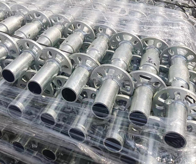
The Ringlock Standard serves as the primary load-bearing vertical component. Engineered rosettes are welded at fixed intervals, typically every 0.5 meters. These rosettes allow for multi-directional, 8-point connections, creating a highly adaptable framework. The standard is made from high-strength galvanized steel tubing. The rosettes feature small holes for right-angle connections and larger slots for diagonal braces. This design eliminates the need for loose fittings and clamps. You simply slide the wedge head of the connecting piece over the rosette and hammer the captive wedge pin into place. Standards come in various lengths, usually ranging from 0.5 meters to 3.0 meters. You stack them vertically using the integrated spigot at the top of each tube. The spigot slides into the bottom of the next standard, and a locking pin secures the joint.
Ledgers dictate the bay length and width, locking securely into the rosettes via wedge pins. Diagonal braces prevent structural sway and ensure lateral rigidity. They reinforce the structural squares, locking the bays into a stable configuration. Ledgers act as both guardrails and structural supports for the decking. They come in precise lengths to create standard bay sizes, such as 7 feet or 10 feet. The wedge head at each end of the ledger fits over the rosette on the standard. Diagonal braces feature a swivel wedge head at each end. You connect them from a lower rosette on one standard to a higher rosette on the adjacent standard. This creates a rigid triangle that stops the scaffold from racking or twisting under load. You must install diagonal braces on the outside face of the scaffold in a continuous zigzag or parallel pattern.
Approved decking options include steel planks and aluminum decks, each with specific load classifications. Access accessories, such as internal ladders, trapdoor decks, and stair towers, are critical for safe multi-tier transit and worker mobility. Steel planks feature a perforated surface for slip resistance and water drainage. They hook directly over the ledgers and lock into place with wind latches. Aluminum decks often incorporate a plywood work surface to reduce weight. For access, you can install internal ladders that pass through trapdoors in the decking. This keeps workers inside the scaffold footprint, eliminating the fall hazard of climbing external ladders. For high-traffic areas or when carrying heavy tools, a dedicated stair tower built from scaffold components provides the safest access route.
Measure precise bay distances and place mud sills and adjustable screw jacks accordingly. Insert base collars onto the screw jacks at the lowest possible adjustment point to establish a solid starting foundation. Proper layout prevents massive headaches later.
Clear and level the ground where the scaffold will sit.
Lay out the continuous mud sills along the planned scaffold line.
Measure and mark the exact locations for the base jacks on the mud sills.
Place the base jacks on the marks and slide the base collars over the threaded stems.
Adjust the nuts on the screw jacks so they are all roughly at the same starting height.
Connect the initial ledgers to the base collars to form a closed, rigid rectangle. Level and square this base bay using a spirit level and tape measure before driving the wedge pins home. This foundational accuracy is non-negotiable. If the base is out of square, the entire structure will twist as it goes up.
Slide the wedge head of a ledger over the rosette on a base collar.
Insert the wedge pin loosely. Do not hammer it tight yet.
Connect the remaining ledgers to form a complete square or rectangle.
Place a long spirit level on each ledger and adjust the screw jacks until the entire base is perfectly level.
Measure the diagonals of the base bay. Adjust the corners until the two diagonal measurements are exactly equal.
Hammer all wedge pins tight to lock the base bay square.
Insert the first set of vertical standards into the base collars. Use a spirit level to plumb each standard vertically in both directions. Make necessary adjustments at the base jacks to ensure perfect vertical alignment. The standards must sit fully down on the base collars.
Slide a standard over the spigot of each base collar.
Place a magnetic torpedo level on the side of the standard.
Check the plumbness on two adjacent sides of the tube.
If the standard leans, adjust the screw jack slightly or tap the base plate to shift it.
Pin the standard to the base collar if required by the manufacturer.
Add the next level of ledgers at the required deck height. Place diagonal braces from node to node to lock the bay into a rigid, unyielding structure. Secure all wedge pins firmly. This lift creates the framework for your first working platform.
Install the transverse ledgers (width) at the desired height, usually 2 meters above the base.
Install the longitudinal ledgers (length) at the same height.
Attach diagonal braces to the outside face of the scaffold. Connect the bottom of the brace to the base collar rosette and the top to the rosette at the new ledger level.
Hammer all wedge pins tight on the ledgers and braces.
Install scaffold planks, ensuring no gaps exceed allowable safety tolerances. Install top rails, mid-rails, toe boards, and self-closing swing gates to complete the fall-prevention envelope for the working level. The platform must be fully planked from front to back.
Lift the steel planks and hook them over the transverse ledgers.
Engage the wind latches on the bottom of the planks to prevent uplift.
Install ledgers at 21 inches and 42 inches above the deck to serve as mid-rails and top rails.
Attach toe boards around the perimeter of the deck to stop tools from kicking off the edge.
Install a swing gate at the ladder access point.
Add subsequent vertical standards using integrated spigots and locking pins to build upward. Tie the scaffold to the permanent structure based on height-to-base ratios, utilizing wall ties or anchors to maintain stability as the height increases. You cannot build a freestanding tower indefinitely.
Stack the next set of standards onto the spigots of the lower standards.
Insert the locking pins to secure the vertical joints.
Repeat the process of adding ledgers, braces, and decking for the new level.
Install wall ties to the building structure. A common rule is to tie in every 26 feet vertically and 30 feet horizontally.
Use right-angle clamps and scaffold tubes to connect the scaffold ledgers to the mechanical anchors drilled into the building wall.
The fixed-node assembly of modular systems drastically reduces the labor-intensive measuring and aligning required by traditional tube-and-fitting scaffolds. Deploying modular systems can yield substantial labor-hour reductions, accelerating project timelines. Traditional scaffolding requires workers to manually measure the distance between uprights and use heavy wrenches to tighten loose couplers. This process is slow and prone to human error. Modular systems eliminate the measuring tape after the base is set. The fixed lengths of the ledgers automatically space the standards at the correct distance. The wedge-pin connections require only a quick strike with a hammer, rather than tedious wrenching. A trained crew can erect a modular bay in a fraction of the time it takes to build a comparable tube-and-clamp structure. This speed translates directly into lower labor costs and faster access for the following trades.
Engineered rosettes and wedge-lock systems offer superior structural integrity and weight-bearing advantages. These systems easily scale to accommodate complex geometries, including circular structures and cantilevered platforms. The rosette connection distributes loads efficiently through the vertical standard. Because the connections are fixed at 90-degree and 45-degree angles, the structure naturally forms strong geometric shapes. You can build massive birdcage scaffolds to support heavy concrete formwork, or erect slim access towers for tight industrial spaces. The modular components allow for rapid scaling. If the project scope expands, you simply add more bays to the existing structure. Specialized components like truss ledgers and lattice girders allow you to bridge wide gaps over entrances or fragile roofs without compromising the load capacity of the working deck above.
Scaffold erectors must use personal fall arrest systems and double-lanyard tie-offs. Advanced guardrail systems provide crucial protection during the progressive erection phase, minimizing fall risks. Erecting scaffold is inherently dangerous because workers are constantly building the platform they stand on. Erectors must wear full-body harnesses with shock-absorbing lanyards. They must tie off to a secure anchor point, usually a rosette on a fully braced standard, before stepping onto an unprotected deck. The double-lanyard system ensures 100% tie-off; the worker attaches the second lanyard before disconnecting the first when moving around the structure. Advanced guardrail tools allow workers to install the top rail for the next level from the safety of the fully guarded level below. This ensures that when they climb up to the new deck, the fall protection is already in place.
Implement standardized status tags to communicate safety status to site workers. Daily inspections must verify wedge pins, structural plumbness, secure decking, and anchor point integrity. The tagging system is the primary communication tool between the scaffold erectors and the general workforce. A green tag means the scaffold is 100% complete and safe for use. A yellow tag indicates the scaffold is safe but modified, perhaps missing a guardrail to allow material loading, requiring workers to wear fall protection. A red tag means the scaffold is under construction, being dismantled, or unsafe, and absolutely no one is allowed on it. The Competent Person must inspect the scaffold before every shift. They check for missing wedge pins, bent tubes, loose wall ties, and damaged planks. Any defects must be corrected immediately before the green tag is signed and dated.
Avoid overloading adjustable base jacks and skipping diagonal braces. Never mix incompatible manufacturer components. Ensure all wedge pins are fully secured with a hammer and always account for wind loading factors. One of the most common mistakes is extending the screw jacks too far, which creates a weak point at the base of the standard. Always keep the extension within the safe working limit. Skipping diagonal braces to save time or provide clear access will compromise the entire structure, leading to catastrophic collapse under load. Mixing parts from different brands voids the engineering certifications, as the tolerances and metal grades vary between manufacturers. Failing to hammer the wedge pins tight allows the ledgers to shift, causing the scaffold to rack. Finally, wrapping a scaffold in debris netting without adding extra wall ties will cause the structure to act like a sail, pulling it away from the building in high winds.
Conduct a thorough site assessment to determine soil bearing capacity and identify overhead hazards before ordering equipment.
Select the appropriate scaffold duty rating and component configuration based on the specific trades and material loads expected on the platform.
Establish a strict daily inspection routine utilizing the green, yellow, and red tagging system under the supervision of a Competent Person.
Train all erection crews on the mandatory use of double-lanyard fall protection and the correct sequencing of modular components.
A: Erection time depends on bay size and crew experience, but modular systems typically assemble 50% faster than traditional tube-and-clamp methods due to fixed connection points.
A: While systems can exceed 100 feet, anything over standard regulatory limits requires a professional engineer's design to ensure structural stability.
A: A legally defined Competent Person must supervise the erection process, even if the general crew is performing the physical labor.
A: The standard is the vertical load-bearing post, while the ledger is the horizontal connecting bar that dictates bay dimensions.
A: Inspections are required before each work shift, after severe weather events, and following any structural alterations.
A: Yes, adjustable base jacks compensate for elevation changes, allowing crews to maintain a perfectly level base lift.
A: Mixing components from different manufacturers introduces severe safety risks and liability issues and should never be done without explicit engineering approval.


