


Tel: +86-131-8042-1118
E-mail:
E-mail:
26 Huanghai Road, Leting Economic Development Zone, Hebei Province, China


Views: 0 Author: Site Editor Publish Time: 2026-08-02 Origin: Site


Construction site safety and project labor costs tie directly to scaffolding assembly speed and structural integrity. Traditional tube-and-clamp setups demand specialized labor and excessive time to erect, causing severe schedule inefficiencies. A modular system scaffold solves these exact field challenges. It provides fixed connection points that streamline the erection process while maintaining rigorous safety standards.
Improper assembly or selecting the wrong scaffolding architecture introduces severe operational risks. Structural failure, regulatory compliance violations, and project delays frequently stem from complex erection processes on non-linear or high-load structures. When components are mismatched or ground preparation is ignored, the entire structural stability is compromised, endangering workers and materials.
This guide covers the exact assembly sequence and component integrity evaluation. You will learn how to determine proper tie-in and bracket intervals, assess ground conditions, and choose the right scaffolding architecture to meet specific project load and height requirements safely.
Standardized Assembly Reduces Labor: Modular system scaffolds rely on fixed connection points (nodes/rosettes), which drastically reduce the time and specialized labor required compared to tube-and-clamp systems.
Base Preparation is Non-Negotiable: The structural integrity of any system scaffold depends entirely on ground assessment, proper mudsill/sole board distribution, and precise leveling of the initial base jacks.
Diagonal Bracing Dictates Lateral Stability: Proper installation of components like the Ringlock Diagonal Brace is critical for preventing lateral sway, resisting wind loads, and maintaining load capacity at height.
System Selection Impacts ROI: Choosing between Ringlock, Cuplock, or proprietary modular systems requires evaluating the specific geometric complexities (e.g., curved vs. straight facades) and load-bearing demands of the construction site.
Before assembly begins, project managers and erectors must understand the precise engineering function of each modular component. Knowing how these parts interact ensures load capacity, structural stability, and safety standards are consistently met across the entire structure. Erectors deal with heavy steel components that must lock together perfectly. A single missing wedge pin or loose cup can compromise an entire scaffold bay.
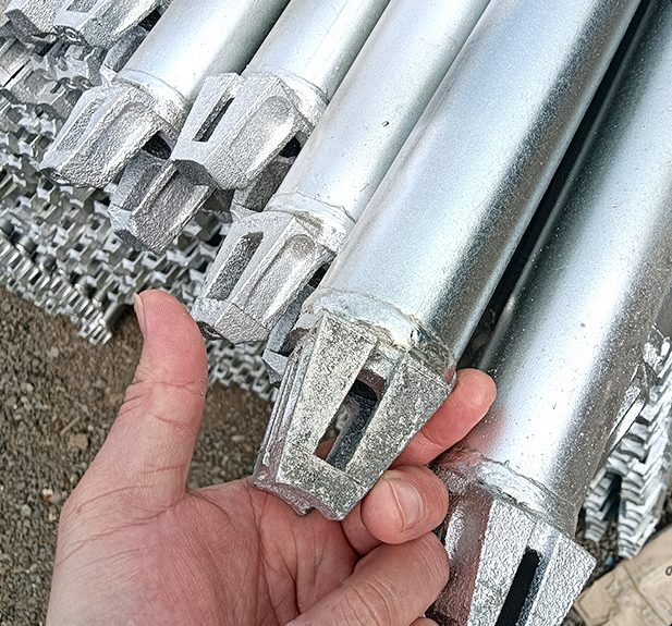
Vertical standards are the primary load-bearing tubes that transfer dead and live loads directly to the ground. These uprights feature fixed connection points, such as rosettes or cups, spaced at standard vertical intervals. This spacing, typically around 19.5 inches or 500 mm, allows for predictable and uniform platform heights. Standards are manufactured from high-yield steel tubing, usually 48.3mm in outer diameter. They come in various lengths, from 0.5 meters up to 3.0 meters, allowing erectors to stagger joints. Staggering vertical joints is a mandatory practice to prevent creating a continuous weak point across the scaffold elevation.
Ledgers provide longitudinal support and tie the vertical standards together, creating the basic framework of the scaffold. Transoms span the width of the scaffold bay. They connect the front and back standards and serve as the direct support structure for the working platform planks. Ledgers dictate the bay length, which directly impacts the load rating. Shorter ledgers create a denser grid capable of supporting heavy masonry loads, while longer ledgers are suitable for light-duty inspection or painting access. Transoms often feature a specific profile, such as a U-shape or O-shape, designed to seat steel or timber planks securely without shifting.
Diagonal bracing is an absolute engineering necessity. The Ringlock Diagonal Brace triangulates the structure to resist shear forces, heavy wind loads, and lateral movement. Without proper diagonal bracing, the scaffold is highly susceptible to sway and potential collapse under dynamic loads. These braces connect from the rosette of one standard to the adjacent standard on a higher or lower level. They feature pivoting wedge heads that accommodate the exact geometric angle required by the bay dimensions. Erectors must install them on both the longitudinal face and the transverse face of the scaffold to ensure complete rigidity.
Adjustable base jacks accommodate uneven terrain, allowing erectors to level the foundation before building upward. Base collars sit directly over the jacks to establish the first node connection close to ground level, providing a secure starting point for the vertical standards. The threaded stem of the base jack allows for fine vertical adjustments. However, erectors must never exceed the maximum extension limit marked on the jack stem. Over-extending the jack introduces severe bending moments that can snap the stem under load. The base collar slides over the jack and provides the initial rosette, ensuring the first horizontal ledgers are positioned as close to the ground as possible.
Side brackets extend the platform width toward the building face, bridging gaps between the main scaffold and the structure. Because they alter the system's center of gravity, side brackets require specific structural support and careful load calculation to prevent cantilever deflection. Brackets typically come in one-board, two-board, or three-board widths. When installing side brackets, erectors must ensure the opposite side of the scaffold is adequately tied to the building to counter the eccentric load. If the scaffold is freestanding, adding side brackets can easily cause the entire structure to overturn.
Component | Primary Function | Material Specification | Field Inspection Focus |
|---|---|---|---|
Vertical Standard | Transfers vertical loads to the ground | High-yield 48.3mm steel tube | Check for straightness and rosette weld integrity |
Ledger | Provides longitudinal bracing | Steel tube with wedge heads | Inspect wedge pins for free movement |
Transom | Supports platform decking | U-profile or O-profile steel | Ensure seating area is free of debris and deformation |
Diagonal Brace | Prevents lateral sway and racking | Steel tube with pivoting heads | Verify pivot rivets are secure and not rusted |
Base Jack | Levels the scaffold foundation | Threaded solid or hollow steel stem | Check threads for damage and ensure nut spins freely |
Thorough site evaluation dictates the success of the entire scaffolding project. Skipping pre-assembly planning leads to foundation settling, overloaded bays, and spatial conflicts with existing structures. Field crews must execute a systematic review of the environment before unloading any equipment from the truck.
Verifying soil bearing capacity is the first step in site preparation. Soft or uncompacted soil requires mudsills or sole boards to distribute point loads from the base jacks over a larger surface area. This prevents the scaffold legs from sinking into the ground under heavy loads. Concrete pads or compacted gravel offer excellent bearing capacity, but wet clay or loose sand requires extensive timber cribbing. Erectors must span mudsills across multiple scaffold legs to create a continuous load distribution path. Never place base jacks directly on bare earth, regardless of how hard the ground appears during dry weather.
Erectors must calculate intended dead loads, which include the scaffold weight, planks, guardrails, and brackets. Live loads account for workers, building materials, and tools. These calculations determine the necessary bay sizing and whether the scaffold requires a light, medium, or heavy-duty rating. Light duty supports 25 pounds per square foot (psf) and is meant for inspection or painting. Medium duty supports 50 psf, suitable for bricklaying or plastering. Heavy duty supports 75 psf and is required for stone masonry or heavy material storage. Exceeding these ratings causes immediate structural deflection.
Mapping the scaffold footprint against building facades is essential. Identify required stand-off distances, note circular or non-linear profiles, and plan around architectural features. Always identify overhead hazards, particularly high-voltage power lines, to maintain mandatory clearance distances during erection and use. Erectors must maintain at least 10 feet of clearance from insulated power lines and more for uninsulated lines. Additionally, map out underground utilities. Heavy scaffold loads can crush shallow pipes or vaults, leading to catastrophic ground collapse beneath the base jacks.
Conduct a visual inspection of the entire ground surface to identify soft spots, trenches, or uneven slopes.
Determine the required load duty (light, medium, or heavy) based on the trades using the scaffold.
Measure the building facade to calculate the exact number of bays, ledgers, and standards required.
Locate and mark all overhead power lines and establish physical warning barriers.
Identify tie-in points on the permanent structure capable of withstanding pull-out forces.
Erecting scaffolding requires a strict, sequential protocol. Adhering to these steps mitigates assembly risks and ensures structural tolerances are maintained from the ground up. Field crews must work methodically, verifying level and plumb at every stage.
Begin by positioning mudsills and adjustable base jacks based on the predetermined grid layout. Set the base collars over the jacks. This creates the foundational node where the first horizontal connections will be made. Space the jacks accurately using a ledger as a measuring guide. Ensure the mudsills sit flat against the ground without rocking. If the ground slopes, start the layout at the highest elevation point. This allows you to adjust the jacks downward as you move to lower ground, ensuring you do not run out of thread extension on the lower jacks.
Connect the initial ledgers and transoms to the base collars. Use a spirit level to ensure the base layout is perfectly level, plumb, and square before locking or wedging any connections. An out-of-square base amplifies errors exponentially at higher elevations, making the entire structure unstable. Check squareness by measuring the diagonals of the bay; the measurements must be identical. Once the base is perfectly square and level, hammer the wedge pins tight. This locked base frame dictates the accuracy of the entire scaffold build.
Insert the first vertical standards into the base collars. Secure the next level of ledgers and transoms at the required platform height. Lock the connections firmly. In a Ringlock Scaffolding System, this involves driving home the wedge pins into the rosette. Use a standard scaffolding hammer to strike the wedge pin until it emits a solid ringing sound, indicating it is fully seated. Do not over-strike, as this can deform the wedge. Stagger the vertical standards so that the joints do not all align on the same horizontal plane.
Attach the diagonal braces according to the manufacturer's technical manual. Typically, these are installed every 3 to 5 bays longitudinally and across the transverse faces. This step guarantees structural triangulation and prevents the framework from racking. Install the braces in a continuous zigzag pattern from the base to the top of the scaffold. Ensure the wedge heads of the diagonal braces are fully locked into the rosettes. Never remove a diagonal brace to create access without installing a replacement brace in an adjacent bay.
Install bracket support when extending platforms toward the work surface. Adhere to strict safety standards by installing bracket supports at minimum intervals, such as every 21 feet in height and as close to the top level as possible, to prevent cantilever deflection. Secure the brackets to the rosettes on the inner vertical standards. Place the required number of planks on the brackets and secure them against wind uplift. Ensure the gap between the building face and the bracket platform does not exceed 14 inches to comply with fall protection standards.
Place steel, aluminum, or wood planks securely across the transoms to create the work platform. Erect top rails, mid-rails, and toe boards to prevent fall hazards and falling objects. Integrate ladder access or stair towers for safe vertical movement. Inspect every plank for cracks, rot, or severe bending before installation. Lock steel planks into the U-transoms to prevent lateral shifting. Install toe boards tightly against the outer standards to ensure tools or debris cannot be kicked off the platform edge.
Follow height-to-base ratio rules to maintain stability. In the US, the 4:1 rule applies, while high-wind regions may require a 3:1 ratio. Install physical wall ties to anchor the scaffold to the permanent structure, preventing the scaffold from tipping away from the building at height. Use mechanical anchors or cast-in ring bolts attached to the building facade. Connect the scaffold to the anchors using scaffold tubes and right-angle couplers. Install ties at the nodes where standards and ledgers intersect to maximize the structural strength of the tie-in point.
Selecting the right modular system depends heavily on site complexity, architectural geometry, and load requirements. Comparing dominant systems helps ensure optimal project execution. Using the wrong system forces erectors to improvise, which immediately voids manufacturer warranties and introduces severe safety hazards.
Feature | Ringlock System | Cuplock System |
|---|---|---|
Node Connection | Rosette with wedge pins (up to 8 connections) | Top and bottom cups (up to 4 connections) |
Flexibility | High; accommodates varying angles and curves | Moderate; best for linear, straight facades |
Application | Complex industrial, circular structures, heavy loads | Standard masonry, straightforward commercial builds |
Labor Efficiency | Fast assembly due to multi-directional nodes | Fast assembly for straight runs |
Maintenance | Wedge pins require periodic inspection for deformation | Cups require cleaning to prevent mortar buildup |
Ringlock systems offer multi-directional capabilities, allowing up to eight connections per rosette at varying angles. This makes them highly flexible for angled scaffolding requirements, complex facades, and heavy industrial applications. The rosette design allows erectors to build circular scaffolds around tanks or silos without requiring specialized curved components. The wedge pin locking mechanism provides a rigid, positive connection that resists vibration from heavy machinery or wind.
Cuplock systems utilize a top and bottom cup mechanism securing up to four horizontals in a single action, making them highly efficient for straightforward, linear masonry work. Erectors drop the ledger ends into the bottom cup and hammer the top cup down to lock the node. This system is incredibly fast for straight walls but lacks the angular flexibility of a rosette system. Cuplock is highly popular in residential construction and basic commercial blockwork.
Mapping system features to project outcomes is vital. Higher initial material costs for advanced modular systems are frequently offset by significantly reduced labor hours during erection and dismantling, alongside superior adaptability to complex architectural designs. Project managers must evaluate the total labor spend rather than just the rental cost of the steel. A system that saves three days of erection time easily pays for its higher rental premium.
Maintaining a safe working environment requires strict adherence to regulatory and operational standards. Continuous inspection and risk mitigation prevent catastrophic failures. Scaffolding is a dynamic structure that shifts and settles under load, requiring constant vigilance from site management.
A designated Competent Person must oversee the erection, dismantling, and alteration of the scaffold. This individual is responsible for identifying existing and predictable hazards and has the authority to take prompt corrective measures to eliminate them. The Competent Person must possess documented training and field experience specific to the modular system being erected. They dictate the tie-in patterns, verify load calculations, and sign off on the daily inspection tags before any workers access the platforms.
Daily inspections are mandatory. The Competent Person must check for plumb and level, verify that wedge pins are fully seated, and inspect planks for deflection or damage. They must also verify bracket attachments and ensure base jacks remain secure and properly distributed on mudsills. Look for unauthorized modifications, such as removed guardrails or missing diagonal braces. Workers frequently alter scaffolds to gain better access to their work; the Competent Person must identify and correct these dangerous alterations immediately.
Frequent implementation errors compromise safety. These include omitting diagonal braces, exceeding the maximum extension of base jacks, failing to install adequate wall ties, or overloading cantilevered side brackets. Avoiding these errors requires strict discipline and adherence to the manufacturer's technical manual. Another common failure is mixing components from different manufacturers. Even if parts look similar, slight variations in steel grade or tube diameter can cause node connections to fail under heavy loads. Always use a single, unified system from a verified supplier.
Building a system scaffold safely requires strict adherence to manufacturer technical manuals, precise base preparation, and a deep understanding of lateral and vertical load dynamics. Skipping steps or ignoring ground conditions will compromise the entire structure. When choosing a system, evaluate the geometric complexity of the project, the required load capacity, bracket extension needs, and the availability of skilled erectors. Match the scaffolding architecture to the specific demands of the building facade.
Consult with a scaffolding engineer to design tie-in patterns and verify load capacities for any build exceeding standard height limits.
Request technical load data and assembly manuals directly from the manufacturer to ensure your field crews follow exact specifications.
Implement a strict daily inspection protocol managed by a designated Competent Person to catch unauthorized modifications.
Contact a reputable supplier to specify and quote a modular system tailored exactly to your site geometry and load requirements.
A: A system scaffold uses prefabricated components with fixed connection nodes, allowing for rapid, standardized assembly. Tube and clamp scaffolds rely on loose pipes and separate fittings, requiring more time and skill to measure, level, and connect at variable angles.
A: You must use a spirit level on the initial ledgers and transoms during the base level assembly. Adjust the threaded base jacks up or down until the entire foundational grid is perfectly level, plumb, and square before adding vertical standards.
A: Diagonal braces are required during the initial erection phase and must remain in place. They are typically installed every three to five bays longitudinally and across transverse faces to provide structural triangulation and resist wind and shear forces.
A: Side bracket supports must be installed according to the manufacturer's specifications to prevent cantilever deflection. A common industry standard is to install bracket supports at least every 21 feet in height and as close to the top working level as possible.
A: In many jurisdictions, including under OSHA regulations, scaffolds exceeding 125 feet in height must be designed by a registered professional engineer. Always consult local regulations and manufacturer guidelines for specific height restrictions.
A: Calculate load capacity by adding the dead load (weight of the scaffold components, planks, and brackets) to the live load (weight of workers, tools, and materials). Compare this total to the manufacturer's duty ratings (light, medium, or heavy-duty) for the specific bay size.


