


Tel: +86-131-8042-1118
E-mail:
E-mail:
26 Huanghai Road, Leting Economic Development Zone, Hebei Province, China


Views: 0 Author: Site Editor Publish Time: 2026-06-29 Origin: Site


Structural integrity defines the boundary between a successful project and a catastrophic failure in complex scaffolding builds. Erecting tall temporary structures introduces immense physical stress. Environmental variables like wind shear and dynamic live loads constantly threaten stability. The primary function of proper bracing is mitigating this lateral movement. It prevents structural collapse under heavy operational load and constant environmental stress. Unbraced frameworks easily sway, buckle, and compromise worker safety on the job site. This article explores the mechanical necessity and practical realities of diagonal bracing. We aim to provide procurement managers, safety engineers, and contractors with an evidence-based framework. You will learn how to evaluate, select, and implement a robust Ringlock diagonal brace. We will cover material specifications, installation risks, and structural integration. True project efficiency depends entirely on understanding these crucial safety components.
Unbraced or poorly braced temporary structures present severe liability. They introduce serious safety hazards and project delay risks. Without proper support, tall scaffolding frameworks remain vulnerable to sway. They can buckle suddenly under shear forces. You transform weak rectangular scaffold bays into rigid triangular frames by installing proper bracing. Triangles offer inherent geometric stability. A diagonal brace effectively transfers horizontal loads down to the base. It disperses forces generated by heavy winds and dynamic worker movement. This dispersion prevents concentrated stress points.
The brace interacts directly with the rosette node. It locks the vertical standards and horizontal ledgers into a fixed spatial configuration. This multi-directional connection prevents independent component movement. Node rigidity acts as the backbone of the entire structural framework. When wind hits the scaffolding face, the bracing network channels the energy diagonally. The energy travels safely into the ground plates.
A stable structure requires perfect alignment between load-bearing assumptions and engineered component specifications. Every piece must pull its designated weight. Success criteria demand strict adherence to load-bearing limits. When contractors substitute inferior braces, they alter the engineered load paths. This alteration invalidates safety margins. You must ensure field installations mirror the original engineering drawings exactly.
Best Practices for Structural Mechanics:
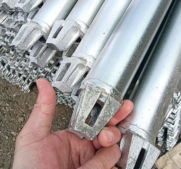
Let us look closely at the physical anatomy of the brace. It features a high-strength hollow steel tube. You will find swiveling wedge heads welded at each end. These heads contain captive wedge pins. The captive design prevents workers from dropping and losing crucial hardware from high elevations. Dropped pins create dangerous strike hazards below. The hollow tube design maximizes strength-to-weight ratios. It provides massive compressive resistance while remaining light enough for manual handling.
Mechanical integration centers entirely on the rosette connection. Swiveling heads align smoothly with the small or large holes of the ringlock rosette. This clever geometry accommodates various structural shapes. It allows builders to create circular, curved, or straight scaffolding runs. Industrial sites often require complex shapes to navigate around massive boilers or storage tanks. The swiveling action provides the necessary rotational freedom during installation.
The diagonal brace never functions as a standalone fix. It relies entirely on the tight tolerances of a complete Ringlock scaffolding system. It must integrate seamlessly to function exactly as designed. Loose connections degrade the overall rigidity. System cohesion requires every wedge pin to fit perfectly into its corresponding rosette slot.
Core Anatomy Breakdown:
Material quality dictates structural performance. You must insist on high-tensile steel for load-bearing parts. Industry leaders typically use Q345 steel grades for structural components. Q345 offers a higher yield strength compared to standard Q235 steel. Lower-grade alternatives pose severe risks under heavy operational loads. They bend or fail unexpectedly when subjected to sudden environmental stress.
Standard tube diameters generally measure 48.3mm. Wall thicknesses range from 2.5mm to 3.2mm. We emphasize tight dimensional tolerances during procurement. Even slight manufacturing deviations drastically reduce buckling resistance. A thinner tube wall saves material costs initially but exponentially increases failure probabilities.
Rust acts as a silent structural destroyer. Frame hot-dipped galvanization as a mandatory feature. It guarantees longevity and safety on wet job sites. Hot-dipped zinc layers resist physical impact far better than inferior paint. They also outperform thin electro-galvanizing. Zinc fully coats the interior and exterior of the hollow tube. This prevents internal corrosion.
Verifiable third-party testing guarantees safe operation. Look for validation from SGS or TUV. Compliance with international standards remains critical for legal protection. Check for EN 12810/12811, OSHA, or AS/NZS alignment. These frameworks provide standardized testing methodologies for load capacity and material deformation.
| Feature Category | Industry Standard Requirement | Inferior Alternative (Risk) |
|---|---|---|
| Steel Grade | Q345 (High tensile strength) | Q235 or uncertified scrap steel |
| Wall Thickness | 2.5mm to 3.2mm | Under 2.5mm (High buckling risk) |
| Corrosion Protection | Hot-Dipped Galvanization (Interior & Exterior) | Paint or Electro-galvanizing (Flakes easily) |
| Certification | EN 12810 / OSHA / SGS Verified | In-house claims only (No third-party proof) |
Field execution often diverges from engineering drawings. Address the dangerous "missing wedge" reality immediately. Crews sometimes erect bays without adequate diagonal bracing. They skip this crucial step to save time during aggressive project schedules. This creates a compounding structural risk. An unbraced section acts like a weak link in a chain. It transfers unintended stress to adjacent bays.
You must enforce strict engagement protocols on site. Workers must apply a firm hammer-strike to fully seat the wedge pin. A loose pin negates the entire structural value of the brace. Visual inspections alone cannot confirm pin seating. Supervisors must perform physical checks to ensure tight mechanical locking.
Forcing incorrectly sized braces into bays causes immediate structural damage. For example, using a brace designed for a 2.0m by 2.0m bay inside a 2.5m bay distorts the vertical standards. This geometry mismatch pulls the uprights out of plumb. It completely compromises the vertical load capacity. Always use the exact brace length specified for the bay dimensions.
Site Supervisor Inspection Checklist:
Common Mistakes to Avoid:
Selecting the right supplier heavily impacts your project safety. Advise buyers to demand extreme quality assurance transparency. You should look for suppliers who readily provide official mill certificates. They must offer accessible batch testing data upon request. Do not rely merely on glossy marketing claims. Authentic suppliers welcome technical scrutiny.
Assess their manufacturing precision during your vetting process. Automated robotic welding ensures consistent strength at the brace head connection points. Manual welding often introduces human error. It creates weak joints vulnerable to stress fractures. Ask for factory floor videos or arrange an inspection tour.
Mixing components from different manufacturers introduces hidden structural risks. Dimensions and steel properties vary slightly between brands. We recommend suppliers who guarantee strict dimensional tolerances across their entire product line. Single-source procurement eliminates compatibility headaches.
Formulate a highly detailed Request for Quote (RFQ). Demand precise technical specifications upfront. Require clear warranty terms and comprehensive compliance documentation before signing any purchase order. Establish your quality baseline early in the negotiation phase.
A: Engineering rules of thumb typically recommend bracing every third or fourth bay longitudinally. However, you must always follow specific engineered drawings. Taller structures or sites facing heavy wind loads often require continuous zigzag bracing across the entire scaffolding face.
A: We strongly advise against mixing components. Different manufacturers use varying tolerances, steel grades, and wedge head designs. Mixing them creates dimensional discrepancies. This practice immediately voids manufacturer warranties and drastically increases your structural liability during an accident.
A: A high-quality hot-dipped galvanized brace typically lasts 10 to 15 years under normal conditions. Severe environmental exposure, such as coastal saltwater or harsh industrial chemicals, reduces this lifespan. Proper storage and routine maintenance significantly extend component viability.
A: You apply the Pythagorean theorem. Calculate the hypotenuse using the horizontal bay length and the vertical lift height as your base and altitude. Most manufacturers provide color-coded length charts. Always refer to these charts rather than measuring tubes manually on site.

